


1. GENERAL DESCRIPTION OF THE PROJECT
1.1. History
Kossuth square accommodates one of the most beautiful and worldwide-known buildings of Hungary, the Parliament. The upgrading of the square aiming at realizing a space fitting with the quality of the building has been for a long time an issue of importance for the Hungarian public life and politics.
Efforts for the renewal of the square have already been made in the past (several concepts were elaborated on this purpose) but in the lack of financial possibilities and in the absence of a strong political will, these remained stuck in the design phase.
The intention of reconstructing the square was presented again to the political decision makers in 2011, as a result of which the National Assembly in a resolution decided about the reconstruction of the environment of the Parliament, Kossuth square
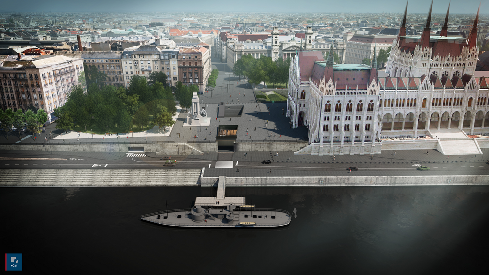
Fig. 1 – Computer-aided visualization of Kossuth square reconstruction (image is presented with the consent of KÖZTI Ltd.)
1.2. Main actors involved in the project
The main tasks to be realized within the frame of the project and the deadline of completing the investment were determined in the resolution, and it was decided that the responsible body of the investment is the Office of the Hungarian National Assembly, as Client.
The specifications and requirements were further detailed in the Steindl Imre Program, elaborated by the Office of the National Assembly, and then set up the program office to coordinate the project. The winning tender of the public procurement for general designing was presented by Középülettervező Ltd. (KÖZTI), who involved in the project as design subcontractors UVATERV Ltd, FŐMTERV Ltd and S73 Ltd. The project management and technical supervision tasks were assigned to ÓBUDA-Újlak Ltd, within the frame of the public procurement procedure. The winner of the General Contractor tender was KÉSZ Építő Ltd, the construction site delimitation and the deep-level car park’s base slab will be completed by Bohn Mélyépítő Ltd, as winner of the sub-tender.
1.3. Design tasks
The task of the co-designers under the management of KÖZTI General Designer was to carry out the full range design activity related to the square landscape design, construction of the deep-level garage and visitor centre and the Parliament Museum, and other related work parts. The aim of the present article is to describe the structure of the reinforced concrete deep-level garage and visitor centre, and the design tasks related to structural engineering. The entire structural design of the facility was elaborated by the experts of UVATERV Engineering Consultants (Department of Metro Design and Structural Engineering).
2. GENERAL PRESENTATION OF THE DEEP-LEVEL GARAGE AND VISITOR CENTRE
2.1. Location
The deep-level garage and visitor centre is located on the north side of the square, in the direct vicinity of the Parliament building. At the west side the facility is separated from the Danube floodplain only by the upper quay retaining wall. The north side of the facility is separated by a street from a six-storey building called America House. At the east side there is a green surface and pedestrian walkways, tram and car traffic streets and buildings. The 110 years old Parliament, which is located at the south side, has a basement of a two-level cellar. The huge building stands on a special plate foundation. The concrete foundation of variable thickness which, under the dome reaches 4,0 m, is a “cyclopean” layer realized with the technology of the epoch of construction, laid in several layers and filled with cement mortar mixed with granular aggregate, ensuring the transmission of the building loads to the load bearing subsoil. At the previous soil investigations, the quality of the different layers showed significant differences of strength. The public utilities disturbing the construction were demolished, reconstructed or treated with special attention. Perhaps it is not an exaggeration to say that the surrounding natural and built environment created special site conditions, resulting in difficult design requirements but a nice task at the same time. These were mainly the preservation of the Parliament building which is a historic monument, and the requirements related to flood risks due to the proximity of the Danube
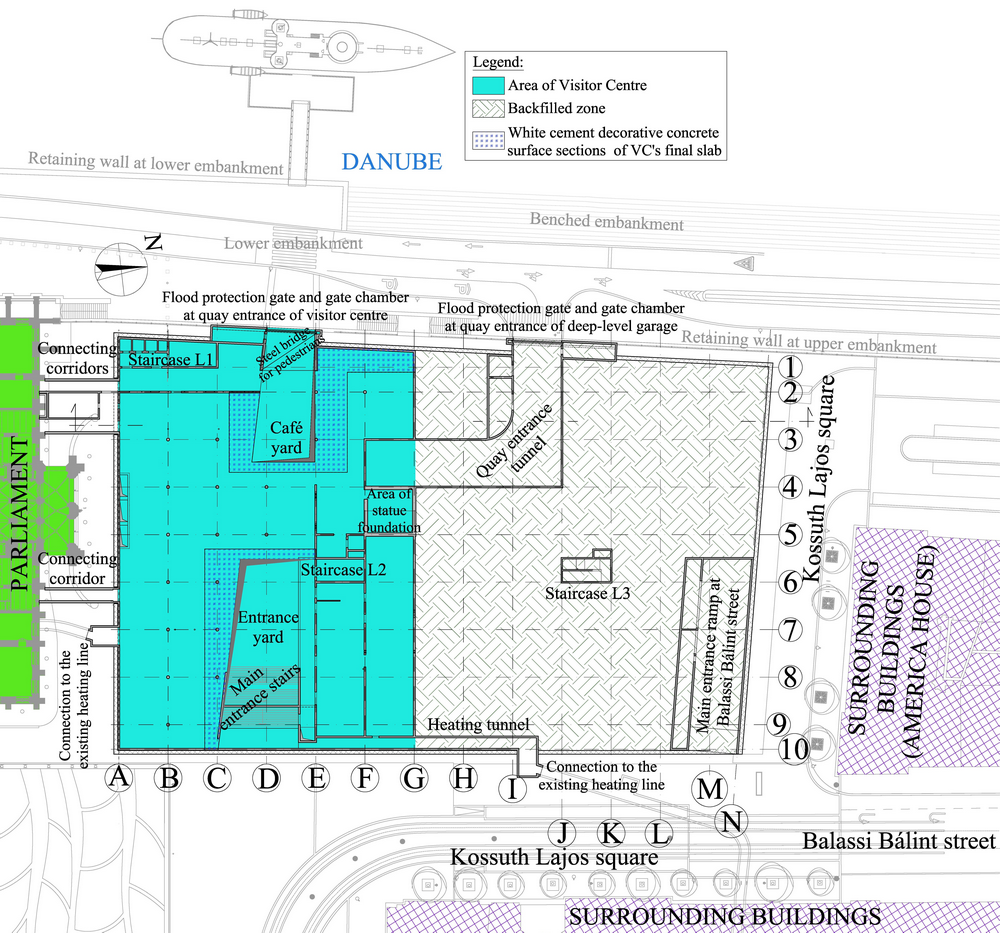
Fig. 2 – Layout after reconstruction with the ground plan of level -1
2.2. General data
On the upper level, basically on the half of the total area of the structure, a sophisticated-presence visitor centre was realized. This facility is connected with a corridor to the Parliament and to the Parliament Museum, which is constructed under the building (the structural design of the latter two facilities was elaborated by KÖZTI). The outdoor connections of the visitor centre are ensured from Kossuth square by the entrance stairs and elevator, and from a pedestrian entrance on the upper quay. On this same level, next to the visitor centre, the closing slab of the deep-level garage is provided with a backfill of 3,6 m, which will serve for future purposes of landscaping of the concerned area. The main entrance of the car park is situated at the Balassi Bálint street side, but driving in possibility is ensured also from the upper quay, where an entrance tunnel leads to the ramp of the deep-level car park. The additional levels can have access through ramps installed under the main entrance. The deep-level garage function is offered on 3 levels; levels -2, -3 and -4 simultaneously offer the capacity for 592 cars, 10 motorcycles and 30 bicycles. Clearance height of level -2 is raised for allowing van traffic, the remaining two levels offer access only for cars. Pedestrian traffic inside the car park is served by three staircases and by elevators installed next to staircase L1. Main inner dimensions of the structure: 72x111m.
The facility had a further important design criterion: the flood protection of the entrances of the visitor centre and the quay entrance of the deep-level car park. Considering the high risk values both places had to be provided with double protection lines: the outer line is a rail guided steel structured flood protection gate of special design, the other is a mobile flood protection wall, which is a finished product. Another important consideration was the static fine-tuning of the foundation zone and the supporting structure bearing the significant dead weight (1.300 metric tons) of the statue to be realized on the surface. The final reconstruction of the demolished district heating line section was also an aspect of great importance, a puzzling task due to the uncertainty of the connection points.
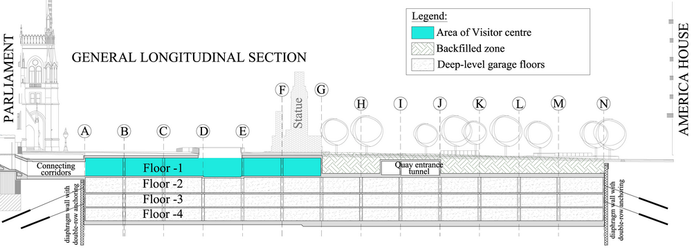
Fig. 3 – General longitudinal section
3. STRUCTURAL ARRANGEMENT
3.1. Delimitation of construction pit and record flooding level on the Danube
According to the soil mechanical report the main characteristics of soil conditions are as follows: the upper layer consists of variable thick and solidity backfill, typically sandy gravel, in some places brick bat of organic materials content. Beneath the backfilling the load supporting layer is compact gravel, sand-sandy gravel. The base rock consists of Oligocene Kiscelli clay. The load bearing capacity of the soil is important, while the permeability capacity is low.
The earthwork surface of garage is determined at approx. 15,50-14,50 m under the existing surface level. Considering that the groundwater level is located significantly higher and the permeability capacity of upper soil layer is important, the construction cannot be realized but with watertight delimitation, therefore a watertight diaphragm wall is to be designed.
The dimensioning of diaphragm wall was realized by using the geotechnical software Plaxis 8 according to the typical cross sections. On the northern, western and eastern sides sizing of one cross section for each was sufficient due to the similar soil structural and surface characteristics. On the diaphragm wall section located on the Parliament side three different cross sections can be found due to the difference between the Parliament building and the structure being constructed. At the load calculations we considered the buildings in the concerned area by a steady loading force exerted on the foundation level, the technological loading of the surface and – for having an economical structure - the water pressure of middle water level of Danube of a 10 years period. At the dimensioning an important attention was given to minimize the deformation of the diaphragm wall and to respect the limit value of 0,2mm for the crack width. The delimitation of the construction was realized by a diaphragm wall of 60 cm thickness with a double-row anchoring, in the angles multi-row steel pipe propping was applied. We designed the diaphragm wall with 4,50 m overlapping beyond the earthwork plane. Due to the importance of the effective watertightness a strict requirement was that the diaphragm wall can be installed everywhere into intact clay - constituting the case rock- at a depth of 3,0 m at least.
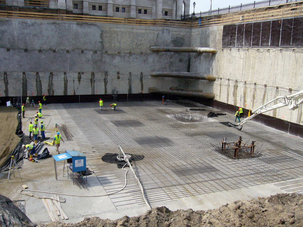
Fig. 4 – Construction pit opened up to the base slab on the Parliament side. Angle pipe carriers, first phase steel construction on 9th May 2013.
We defined the working level of the diaphragm wall at the design water level, 104,53mBf. ensuring the appropriate alignment of waterproofing against the groundwater pressure of the structure. The diaphragm wall was constructed from watertight concrete provided with joint tapes for a better watertightness. The earthwork was realized in three phases according to the anchoring work. The upper anchor line started above the construction water level, while the anchor body is significantly deeper than the design water level. The bottom anchors were realized under water with appropriate technology applied. The distressing of the anchors was approved phase by phase according to the required completion level of the internal floor slabs. After the load release the crossings were to be provided with watertight closure.
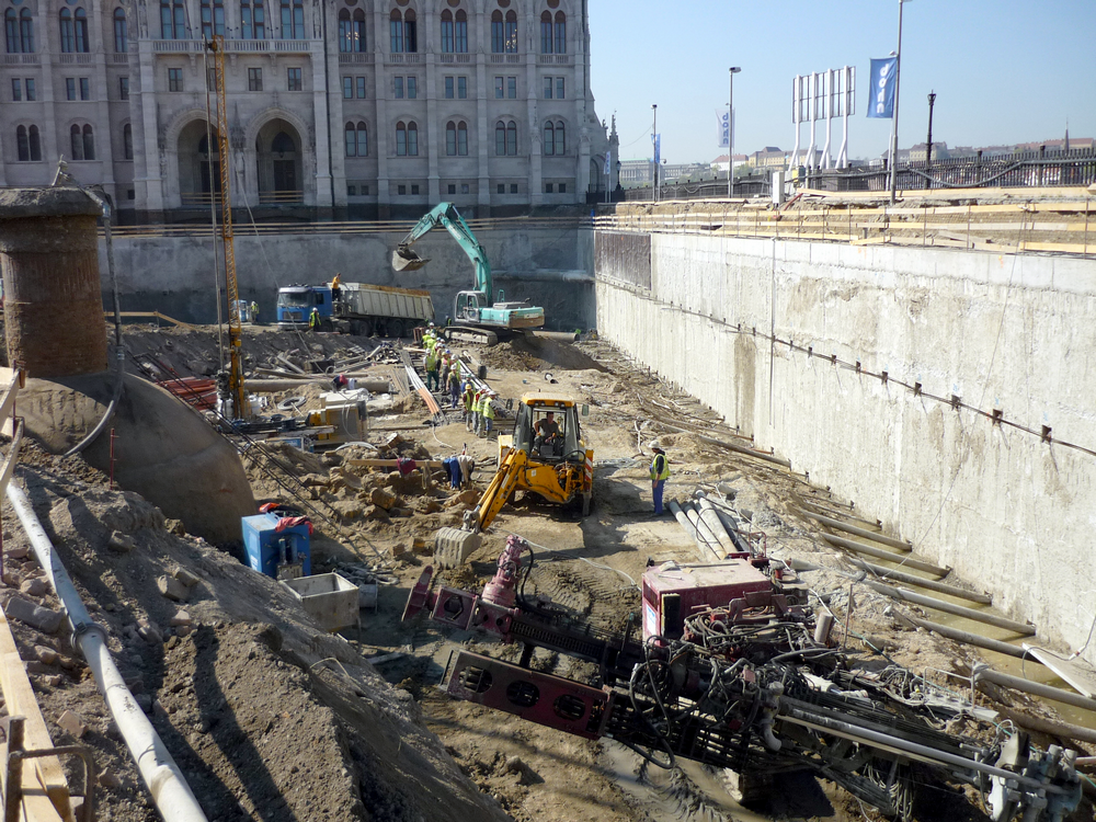
Fig. 5 – Earth excavation up to the 2nd anchor level on the Danube side, boring of underwater anchors on 18th April 2013.
In order to monitoring the motion of the structure we designed installation of 2-2 inclinometer pipes into the approx. third part of the wall on all four sides. The monitoring was to be realized in proper frequency according to the construction phases.
Since there is no appropriate loadable mass above the garage, groundwater level regulation is applied to prevent from uplift. A draining system embedded into a sandy-gravel layer under the base slab of the garage ensures the drainage of the water infiltrating through the soil. Between the diaphragm and inner lining wall the water is drained to the lower levels by superficial drain system. The water collected in wells is pumped by pump facilities into the water drainage system or it is used for the operation of the building. The watertight concrete layer of base slab ensures the appropriate watertightness.
According to the Client’s requirements we had to prepare - in case of diaphragm wall construction area delimitation technology - a uniquely detailed risk analysis determining the measures to be taken in function of - among other factors - Danube water level and the progress of construction. Due to the varied environment, an important part of the factors presented in the risk analysis manifested effectively. Everyday problems emerged concerning anchoring, diaphragm stability, unknown public utility, ammunition, etc. In an optimal case the flood risk did not involved but an accurate measurement and observation. In the most critical cases – important earth excavation and high water level – we also had to consider the artificial flooding during the operation of temporary diaphragm wall. The critical limit was determined in a water level reaching the lower embankment during the earthwork up to the foundation level. The preparedness levels indicated by flood risk analysis were determined in function of overloading allowed and tolerable displacements. The different degrees – according to displacement measurements - were “alert”, “preparedness” and “emergency”. The designed stress capacities ensured the safety requirements. In case of the anchor stresses the safety was tested at the qualification of each anchor. In case of flood, as extraordinary load, the safety requirement approached the basic value of 1,0. The necessary measures to be taken were principally determined in order to limit the deformations to an optimal level. By the increasing of monitoring up to a daily basis the evaluation became a real time process.
The extraordinary flood of 2013 required a special approach of all design. The measures required in frame of the risk analysis were to be realized according to the prognostic of end of May.
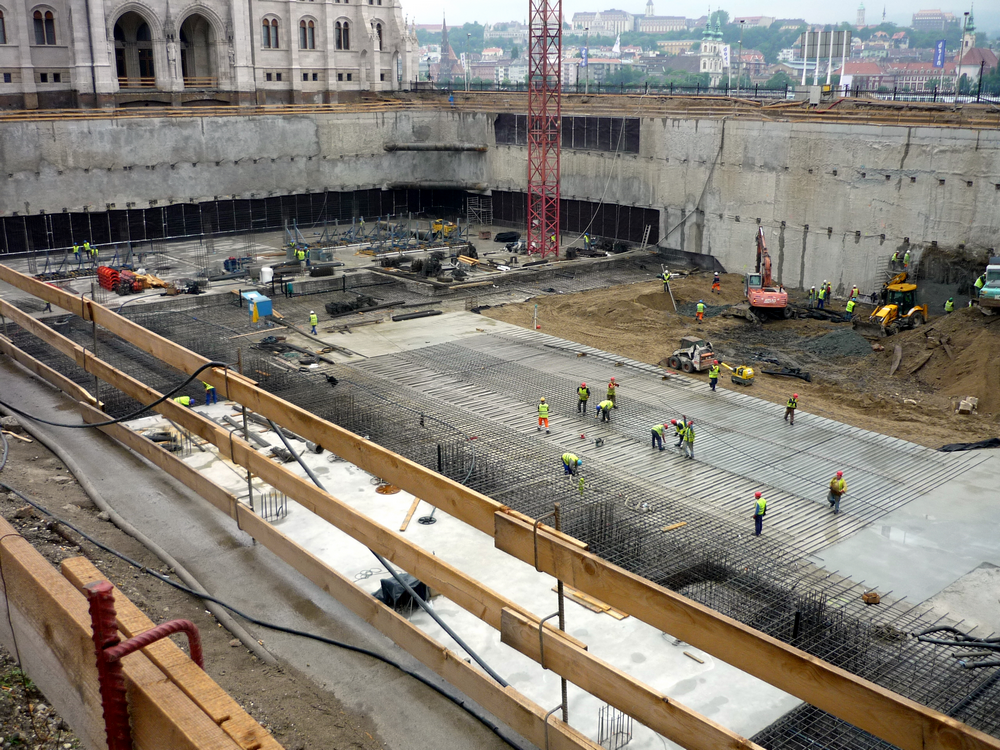
Fig. 6 – Base slab completion level before flooding, from Balassi Bálint Street on 30th May 2013.
Only a short week was given for the conscious realization between the typical and the emergency case including the four days necessary for the backfilling. The backfilling work was completed only just few hours before the total flooding of the embankment. Due to the accurate preparations and the construction of quality according the design, the record height flood – exceeding by 40 cm the maximal level ever observed – had subsided without any definitive damage however involving a delay of 20 days. The pressure measurements realized by the monitoring system ensured information not only for the momentary safety measures but for solving later, similar situations and correcting design parameters.
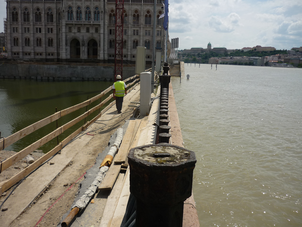
Fig. 7 – Artificial flooding measures taken in the construction pit, with a record outside flood on 10th June 2013.
3.2. The deep-level garage construction
The deep-level garage has been built in an open excavation pit, heading upwards from the bottom, with permanent surface water evacuation, and a conventional reinforced concrete structure. The inner lining wall and base slab have not been tied to the diaphragm wall. Around the external perimeter structures, beds allowing for drainage (a surface drain between the diaphragm wall and the inner lining wall, and a sand gravel drain bed beneath the base slab, complete with an appropriate drainage network) have been installed. They are used to deliver infiltrated water into drainage wells built into the base slab. From these well, water is removed by pumping. So, no water pressure on the deep-level garage structures will build up, and no upfloat had to be reckoned with. In order to ensure an internal water drainage, both the base slab and the intermediate slabs have been built to have a crossfall of 0.5% created from two summits led all along the engineering structure. At the deepest points, small depth gutters have been foreseen. Inner water is evacuated into collectors built in the base slab from where they can be removed by pumping as necessary.
The base slab has been made as an impermeable reinforced concrete structure, in two major structural thicknesses - a thickness of 85 cm at the part beneath Visitor Centre, and 120 cm at the parts concerned by the deep-level garage with backfill and by the statue foundation - adjusted to loads transferred from above. Staircases and sumps have a 60 cm thick bottom plate.
Reinforced concrete columns and wall structures, the mixture of which forms a vertical supporting structure framework, have been built floor by floor by using starter bars out of the base slab.
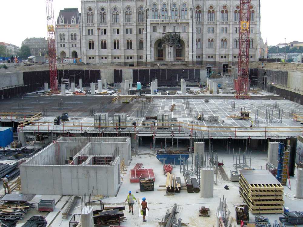
Fig. 8 - An intermediate state of construction on 13th August 2013.
In the general field with intermediate support, the elongated round piers typically with a cross section of 60/110 cm have been arranged in a raster of 8.4 x 8.1 m. At the part affected by the statue foundation, it was necessary to increase pier cross section and to install piers at one corner of staircase L2. In staircases, near the main ramps and at the edges, vertical loads walls are borne by walls with a thickness of 30 cm running all along in full height. In addition, the wall near main ramps running parallel to the diaphragm wall is loaded not only in its plain but it also carries horizontal loads transferred from ramps and ensuring a final support for the excavation pit. Some wall sections have been reckoned with as a wall bearer.
The horizontal load bearing structures are - depending on the load imposed on them - reinforced concrete slabs with different thicknesses which are also used as a final supporting structure for the diaphragm wall. The thickness is 25-30 cm for car park floors, and 85 cm for the final slab having an earth backfill. At some locations, beams are used to transfer load onto piers. Walls and slab structure of embankment tunnel starting from the final slab form a box type framework. At the tunnel exit towards the embankment, and the affected parts of diaphragm wall and existing retaining wall at the upper embankment had to be demolished in order to allow the newly built reinforced concrete structure of deep-level garage exit and gate chamber to be built.
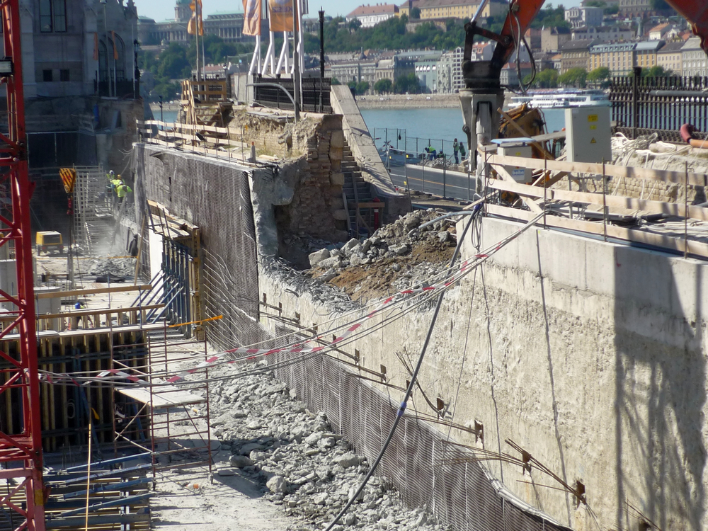
Fig. 9 - Demolishing diaphragm wall and upper retaining wall at the entrance to Visitor Centre and deep-level garage on 5th September 2013.
A cap beam has been installed on the demolished diaphragm wall. The demolished portion of retaining wall had to be restored by connecting it to the new structure. Waterproofing concrete mass insulation and surface insulation are connected on the cap beam. Considering that the entrance is found beneath flood level, a double flood control gate system including a movable slide gate and a mobile mounted wall has been installed. Each flood control system component had to be concreted into the structure in a watertight way, with strict tolerances.
In the structural calculations, each structure has been tested through modelling on a floor by floor basis, using AxisVM 10 structural analysis & design software. For the final slab supported with piers and the intermediate slabs, spot-like and surface supported models have also been developed. The former has been used to calculate bearer reactions and deformations, whereas the latter to perform surface steel reinforcement and crack width tests. Bearers have been taken into consideration with a rigidity calculated from their restraint conditions, network length and cross sections. Support conditions have always been reckoned with according to a vertical supporting structure framework, and for the base slab, a continuous surface support has been used for modelling the load bearing base. Dead loads and payloads have been used to load structural models. For the former, the own weight of structures and the weight of pavement courses overlying them have been reckoned with whereas for the latter, loads imposed by vehicles have been considered as governing combinations of loads. Forces arising in vertical supporting structures have been calculated floor by floor, then, by summing them separately for each type of load, the base slab has been loaded. Pier rating has been calculated floor by floor, dividing them into groups depending on the type of mechanical stress. The concrete applied is of C30/37 strength class, with conventional grey cement dosing. Each rating has been calculated according to latest EUROCODE standards.
3.3. Visitor Centre Structure
Visitor Centre is found on Floor -1, between axes A and G, and is directly connected to the deep-level garage structure. Its floor slab typically has a thickness of 30 cm but at locations where it is not sufficient due to a higher load - for instance, beneath power electric machinery rooms - the thickness has been increased to 35 cm. The walking level of slab is flushed but at several locations a step in level had to be realized due to the different pavement courses. For instance, the entrance and café yard areas are lowered by 20 cm with respect to the general slab level due to waterproofing and thermal insulation. On the Eastern and Western sides, a reinforced concrete structure that supports the main entrance stairs and the steel bridge for pedestrians will transfer their loads onto the slab. Here, a system of beams had to be applied in order to impose the loads transferred, onto piers.
Supporting the final slab of Visitor Centre is generally provided by reinforced concrete piers with a diameter of 50 cm, adjusted to 8.40 x 8.10 m raster of the deep-level garage. At locations where it has not been feasible, reinforced concrete walls have been built a part of which is a continued wall structure of staircase and inner lining walls on Floor -1, and the other part is a single-floor wall bearer built on that floor only. Internal height varies in the range ~3.70 to 4.15 m. Walls generally have a thickness of 30 cm but at locations exposed to a higher load, they have an increased cross section: the wall bearers beneath statue foundation and the walls supporting the steel bridge have a thickness of 60 cm, whereas the structural wall closing the Visitor Centre and exposed to a ground pressure arising from backfill is 35 cm thick.
There is just room enough for the minimum course thickness pavement above the waterproofing and thermal insulation layers installed on the final slab, therefore, the slab is designed to have a slope of 1.5% transversally, following terrain conditions of a new surface to be realized. Typically, it has a thickness of 50 centimetres but at some locations - adjusted to the load - a locally different thickness has been made.
The East-West oriented main corridor of Visitor Centre is roofed in part only: on the Eastern and Western sides, there is no slab above the area concerned by the descending stairs and the steel bridge.
The slab portion and wall system supporting the statue is connected to the final slab of Visitor Centre. The weight of the planned statue featuring a heavy weight (the statue including its supporting structure are out of the scope of a sectoral design by UVATERV) will be transferred as a distributed load, through a base slab, to the reinforced concrete slab of final ceiling slab. At the statue foundation, the supporting system for Visitor Centre and deep-level garage has been adjusted to it, by means of structural solutions already presented.
There are three connections built from the Visitor Centre to the Parliament: a combined corridor of entrance for members of Parliament and visitors, an exit corridor for visitors and a tunnel for public utilities channel. On the side towards River Danube, there is an entrance for pedestrians from the embankment, whose flood control and insulation connections are the same as those of the deep-level garage.
The section of public utilities tunnel for providing the Parliament with heating, crossing the engineering structure has been demolished and aligned in a new route adjusted to the structure.
The structural engineering modelling and calculation of structures have been performed in the same way as described in the previous chapter. As for material quality, strength grade C35/45 has appeared. In addition, several structural elements have been made with white cement dosing, in decorative concrete quality making crack width requirements even stricter.
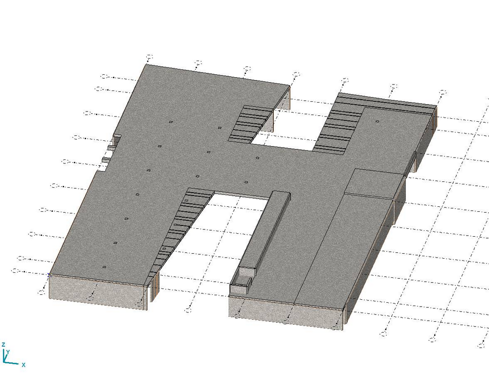
Fig. 10 - A mass model for Visitor Centre final slab.
3.4. Special solutions applied for reinforced concrete structures
Considering that the design and implementation schedule has been extremely tight, even during the design we have striven for applying state-of-the-art technologies and solutions allowing for an acceleration of the pace of implementation, offering a technically appropriate solution and providing cost-effectiveness at the same time.
a) Using finished items and products from construction industry
During the design, finished items and products from construction industry not so widely used in the construction industry practice in Hungary have been used consciously. For the major part, they are not absolutely necessary, with respect to the conventional solutions, in a standard construction environment due to their extra price but in our case their application has been by far economic for the contractor, due to the tight schedule of implementation and to the strict time limits subject to penalties. The products applied have greatly contributed to a rapid, simple and easy-to-overview steel reinforcement installation, thereby reducing manpower demand and time. In addition, within groups of products - in the case where some parameters match - some product are interchangeable with each other, so in certain cases, a "waste" otherwise realized as a loss could also be utilized with a consent thereto from the designer.
For plain plate slabs, the great span, high load and the restricted crack width have resulted in a dense steel reinforcement at pier heads steel reinforced using standard and reinforcing steel reinforcement. Installing the dimensioned puncture type steel reinforcements would have required a great amount of manpower and time if using conventional elements. Realizing puncture type reinforcements by using factory-made products has greatly contributed to a rapid and convenient work.
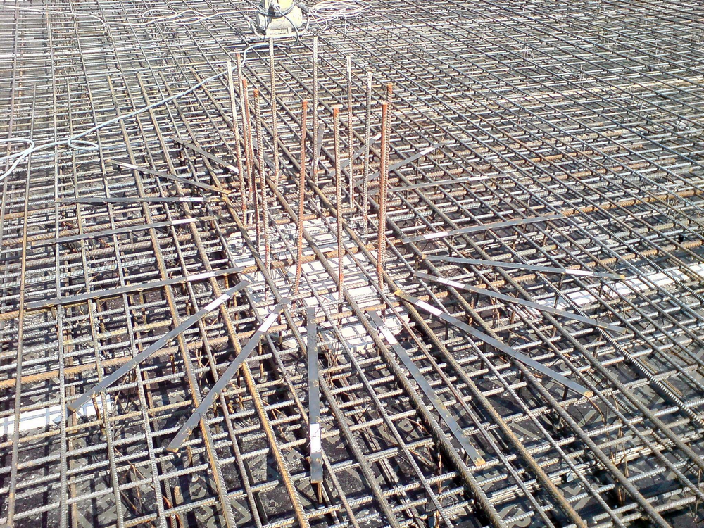
Fig. 11 - Puncture type steel reinforcement with radial arrangement in an intermediate slab on 11th July 2013.
At wall and slab connections not withstanding torque, the "zip-fastener" type reinforcement that can be installed into a formwork has become standard by now, forming a basis for large panel technology. Connections of this kind have also been widely used in this work. In addition, a special version thereof is represented by the so-called composite action anchor hook with clamping edge that connects the structurally dimensioned supporting structure and the concrete slab concreted onto it subsequently in such a way that the waterproofing to be made between both concrete layers can be led through the bars in a watertight manner.
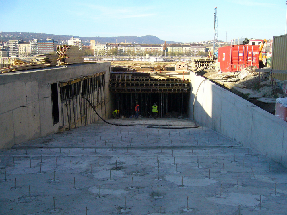
Fig. 12 - Built-in, composite action pins with clamping edge in the main entrance ramp on 2nd December 2013.
Chair distance pieces as standard for slabs have only been used for slabs with great thickness, whereas the steel reinforcement for inner slabs could be accelerated by installing prefab corrugated distance pieces. For an enhanced watertightness, optimum components have been foreseen in each case to seal working joints: starting from surface or inner gap tapes to swelling and/or injectable ones. Concrete placement working joints have also been made using a finished product from construction industry: "streckmetall" (ribbed expanded sheet) tapes have been installed perpendicular to the slab plain in order to obtain a possible fastest and simplest design of working joints.
Armature type installation of steel reinforcement of piers - although they do not represent a product - can also be assigned here. Pier steel reinforcement has been at factory assembled, and clevises fixed using spot-welding on the main steel reinforcement. So, a complete pier armature has been delivered to site. All we had to do was to position it to the right place by means of a crane.
b) Using precast reinforced concrete pieces
The entire underground garage structure can be basically built in an efficient way by using a monolithic technology. For large slab and wall surfaces, it was not justified to use precast elements. However, in order to accelerate the work, we had to do our best, so, for smaller structural units - if allowed by the structural framework as well - it had to be checked for which elements it would be recommended to use precast structural elements. As a result thereof, flights of stairs have been foreseen to be made from precast reinforced concrete units connected through connecting steel reinforcement pieces to monolithic landings concreted simultaneously with them.
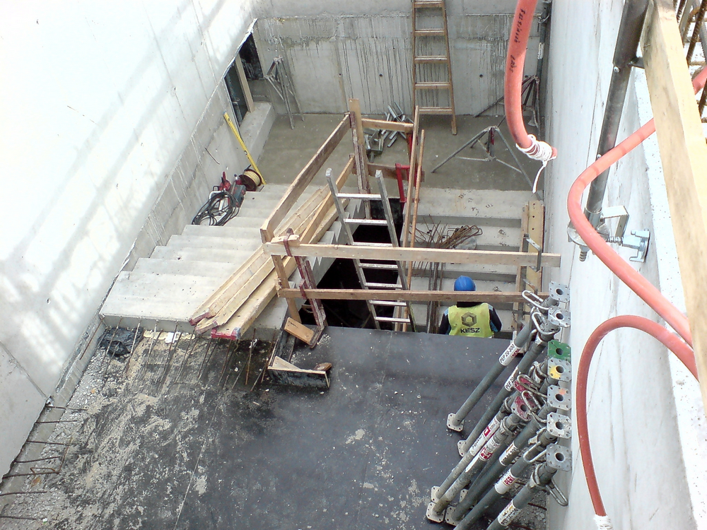 Fig. 13 - Built-in and positioned precast flights of stairs on 19th September 2013.
c) Working joints
For working joint, the primary aspect was to reduce concrete placement stages to a minimum (that is, to maximize the size of panels placed into concrete at the same stage), and to optimize assembly of reinforcement steel pieces for each stage so that the subsequent stage can be concreted as soon as possible. The upper limit of concrete placement limits have been jointly determined by the maximum panel size that can be concreted at the same stage (<35x35 m) and by the amount of concrete that can be worked in on the maximum (<1000 m3). Another condition was represented by a time-limit for concreting opportunity for adjacent panels (according to concrete placement technology, at least 4 days must be provided between the time at which two adjacent panels are concreted), and by selecting the place of working joints adjusted to stresses.
d) Shuttering
For shuttering, the construction meant no particularity. For the major part, routine professional elements have been used. Slabs and walls were shuttered using large panel elements, with the shortest turning time due to the tight schedule. For poles unified in size, the sample shutters could be moved simply. When shuttering a slab, it was a special demand to ensure a temporary support due to the final slab having a great thickness, which remained in place at lower floors as a trimming until the slab has hardened. Here, the use of Peri Skydeck slab shutter system offered advantages, allowing for a recovery of formwork panels with the supporting columns left in place.
Decorative concrete columns at Visitor Centre are made of white concrete. For an aesthetic appearance of round piers, impregnated paper tube has been used as a formwork whose internal coat could ensure a smooth surface without joint.
For the decorative concrete slabs, even the new factory-made panels were not smooth enough, therefore, a layer with tight joint has been fastened separately onto the plank formwork.
3.5. White cement decorative concrete surfaces
Specified walls of the Visitor Centre, round piers with a diameter of 50 cm and some sections of the final slab are designed to have a white cement decorative concrete surface. Due to its shrinking features, the concrete made of white cement only allows for a concrete placement of large surface slab portions in a limited way which has caused a problem requiring a structural intervention mainly for the final slab where - at the sections concerned - a horizontal working joint had to be used to divide slab cross section. The lower decorative concrete crust has been made with white cement dosing, enhanced crack-distributing steel reinforcement and plastic fiber dosing. The upper conventional reinforced concrete bed has been connected to the lower surface through a connecting steel reinforcement. Due to a properly thin cross section thickness of the white cement cross sectional part, no harmful shrinking typical of that material could develop, and the high quality surface could be completed without any crack.
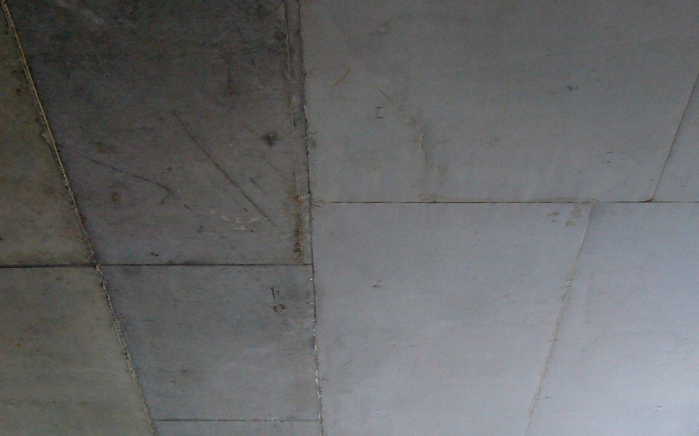 Fig. 14 - Visitor Centre final slab - conventional grey cement surface and white cement surface of decorative concrete quality even before cleaning on 2nd December 2013.
The connecting steel reinforcement for complex cross section has been sized for a sliding force according to principles applied for composite structures.
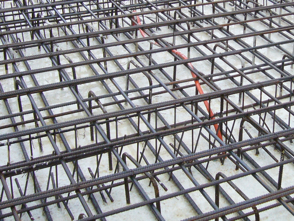 Fig. 15 - Crustal concrete poured with white cement decorative concrete and a more dense distance piece steel reinforcement applied at general section to realize composite action of cross section on 5th November 2013.
The concrete for decorative concrete surfaces has been made using a maximum additive grain size of 8 which is significantly smaller than the usual grain size.
The white cement decorative concrete surfaces have also forced the contractor to apply special solutions. Of them, it is noteworthy as a peculiarity that the steel reinforcement installed into the crust concrete has - in a completely unique manner - not been seated on the formwork but suspended from a temporary supporting structure made from shuttering beams above the white cement field. The reason why a "floating" steel assembly has been worked out was to ensure that even the distance pieces of concrete cover should not appear on the decorative concrete surface having high aesthetic demand.
4. SUMMARY AND CONCLUSIONS
The Underground Garage - Visitor Centre complex at Kossuth tér in Budapest seems to be a simple underground reinforced steel structure. Nevertheless, due to its complexity and highlighted central situation it has had a couple of challenges. The short deadlines for design and construction work could have not been realized without an enthusiasm and high level professionalism of those involved, a proper management and control of the project and a continuous on-line data flow between participants. Due to the short deadline for implementation, it was necessary to foresee every up-to-date component that allowed for an industrial implementation despite custom-designed constructions. Civil engineering requirements have demanded high quality as a basic expectation. Structures have had to comply, to the same extent as that of load bearing capacity, with high aesthetic requirements as well. In practice, every structure had to meet a quality met by decorative concrete. The only difference was in the degrees thereof. Using white cement to a great extent - due to the known sensitivity of that material - has forced to work out customized technologies for steel reinforcement and concrete placement.
With respect to the basic challenges, even the excitements during a 20-day relaxation period when the site was flooded due to a high water level of River Danube never experienced before are not noteworthy.
 Gergely HOLU (1981) MSC civil engineer (Budapest University of Technology and Economics, 2006); Postgraduate engineer-economist (Corvinus University of Budapest, 2013); 2006-2008 designer at CONSULTANT LTD.; Since 2008 designer at UVATERV LTD.; Geotechnical and structural design engineer in numerous Hungarian major investment in the design of construction area delimitation, foundation, external-internal r.c. concrete structures for underground structures and traffic facilities. Among them can be mentioned the participation in the detailed design work of Bátaszék tunnel, the detailed design work of stations of Pester side of Budapest metro line 4. section I., as well as the Kossuth Square deep-level garage and Visitor Centre, subject of present article. Further references: building structural designs, steel- and r.c. concrete structures. Beside the design work, realization of regular designer foreman tasks, coordination between branch offices and with other persons involved. Member of several professional associations (e.g. Hungarian Group of fib). Member of Presidency and vice president of Hungarian Tunneling Association.
 Csaba PETHŐ (1948) MSC civil engineer (Budapest University of Technology and Economics, 1972); Designer Engineer at UVATERV LTD. until now. Participation in design works of Budapest metro Northern and Southern line as structural designer. Other references: delimitation of construction pit by diaphragm wall method of buildings in Budapest and in the country; pile-diaphragm wall foundations; structural design of buildings with r.c. concrete, steel, brick, wood structure. Buildings and retaining walls of motorway engineering sites with pile, back anchoring, gabion technologies. Railway tunnel on the Hungarian-Slovene railway line beneath Ballahegy. Channel Tunnel detailed design at Mott Hay & Andersen Ltd., design of Calcutta metro tunnel section in India, technology training ant control. Structural design of Libyan Tripoli metro network. Consultant for students, lecturer at Budapest University of Technology and Economics and other Hungarian universities.